Go to 🎨 Design
🖌️
UX design
(79)
🎨
UI design
(49)
🖌️
Product design
(48)
🎨
Graphic design
(40)
💡
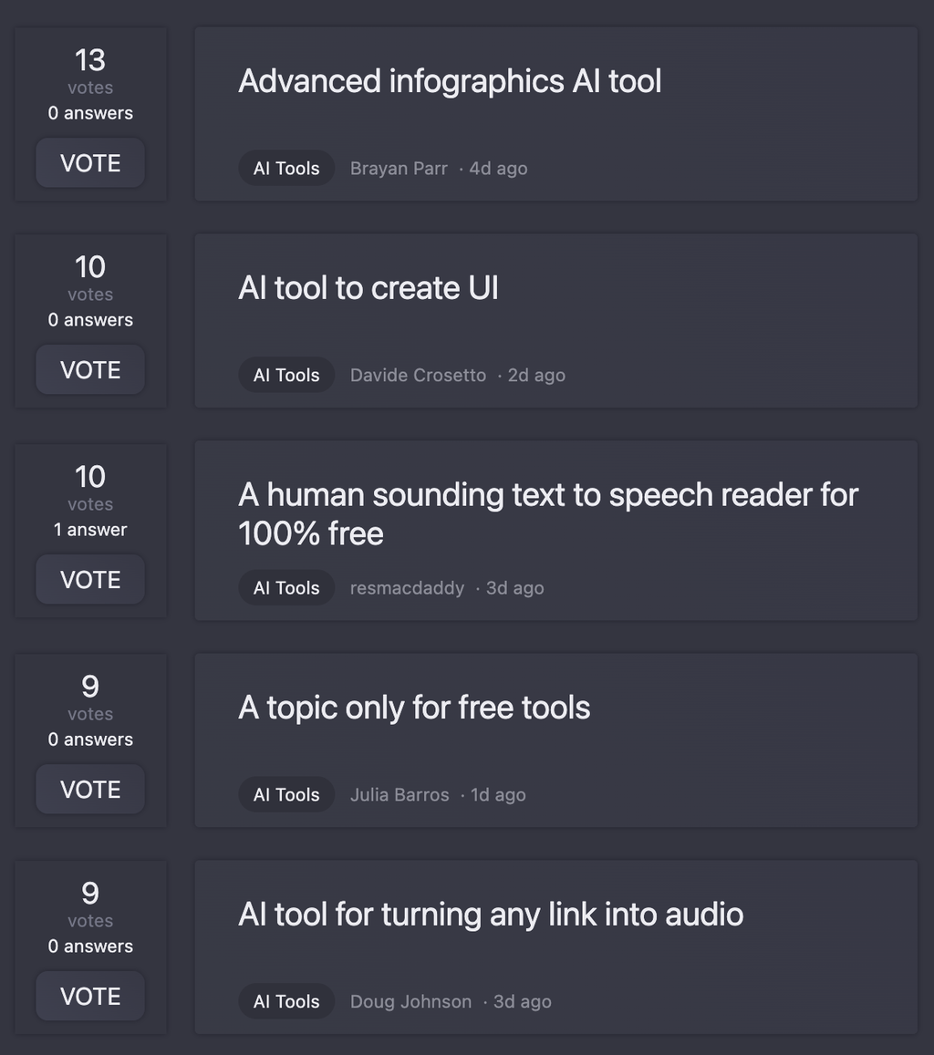
Design ideas
(12)
🌟
Design feedback
(12)
🔌
Circuit design
(6)
🎨
Design thinking
(3)
🧵
Fashion design
(3)
🖥️
UI
(0)
🔍
UX
(0)
 Kolors AI
 Canva Visual Suite
 LookX
LookX
 Drawnaq
 Design0
 Veeso AI
 Variant
 ArtiVisio
 Idea to Design
 Perspective Pioneer
 Figma AI
 Figma Make
22,631
9,290
3,859
991
831
723
415
298
287
159
139
135
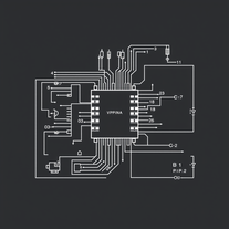
Circuit design
taaft.com/circuit-designThere are 5 Free AI tools for Circuit design.
Get alerts
Number of tools
5
▼ Latest
Free mode
100% free
Freemium
Free Trial
Top featured
Specialized tools 5
-
 Transform text descriptions into professional circuit diagrams instantly.
 -
 AI-powered circuit design for everyone
 -
 AI-powered schematics for precise electronic designs.
 -
 Turn text into detailed circuit diagrams instantly.leighton Bankes🙏 4 karmaMay 19, 2025@Text To Circuit Generator AiI thought this was going to generate a circuit, but it generates a stylised pictures of a circuit with no information
 -
 AI-powered circuit design for current generators